Its been a while since I've put a new page up for various reasons ( work mostly), I have been stuck in Diff rebuild hell from Oct. until May 2005. I never would have come close to solving this if not for the expertise and determination of Dick Vandermeyden. If you don't have a mill, lathe and all the associated experience making parts don't consider changing out your rear end gears.
After cleaning and prepping all the parts I hauled it all down to Dick's shop and we got started. We found all sorts of issues in the first week. Worn parts which were not usable, parts that didn't fit and were not exactly the same as the originals. Missing and incorrect bearings. We divided the project into 4 areas, output shafts, ring gear and clutch pack, Pinion, and finial setup. Both Dick and I read the Diff section in the shop manual as well as the paper work which came with the new ring and pinion several times before starting, hours of discussion followed about how to recreate the setup tools shown in the Shop manual. The Reider Racing Ring and pinion kit was good quality but not exactly the same as the original parts. The documentation was ok, but it assumed you were putting the gears in a later non Independent Axle housing so no mention of the output shafts was made.
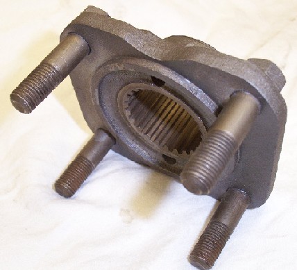
First problem, some "qualified" jaguar mechanic along the way put the output shafts together incorrectly, stacking the shims that should have gone between the two roller bearings to prevent end play, between the outer bearing and the output flange. The result was that the output bearings had end play and slapped back and forth on the shims and output flange. This ruined the shims and output flange and left me with two flanges which were worn down on the inside face as much as .060, Dick found a new pair of good output flanges and we used these to setup the output shafts. What is pictured is the ruined output flange. I this picture doesn't show the side that is worn. It was the best picture I had.
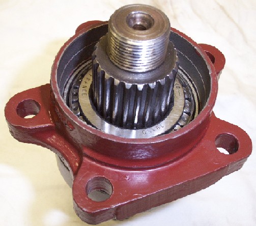
I source four of the correct Timkin output shaft bearings from International bearings $50 each! (not included in the kit from Reider Racing), then opted to make a custom spacers to set the end play between the bearings. Normally this would be done with shims and a standard sized spacer, but the shims were trashed. Dick had some Stainless pipe the right size to make a spacer which was exactly right. An added advantage of the custom spacer is that since there is no shim pack there is nothing to loose in the next rebuild and no way to put it together wrong. Thick shim packs also have a tendency to compress over time which can allow more end play than recommended.
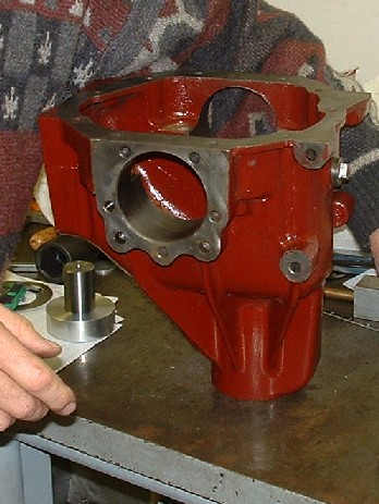
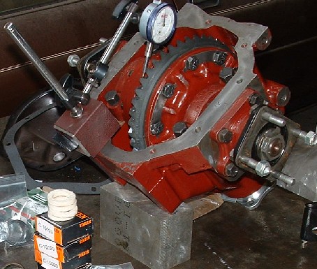
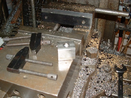
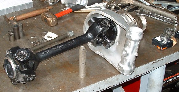
After the output shafts were complete we put the Ring gear on the clutch assembly. The original Ring gear had larger bolts and so the housing had larger holes to take these bolts. We had to make ten spacers to adapt the new ring gear to the older housing. We made these out of stainless steel with the correct OD and ID to take up the delta between the new and old bolt sizes. After this was complete we did some test fitting shown here, to see how far the pinion was out when mating the ring. We determined at this point that we were way off, the pinion was much to short mating the ring gear even with all the shims we had behind the inner bearing cup. At this point we had to stop and regroup. We needed tools we didn't have to determine how to setup the pinion and we needed to reference the tools and the setup with another Diff which was thought to be original and setup correctly.
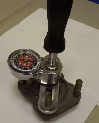
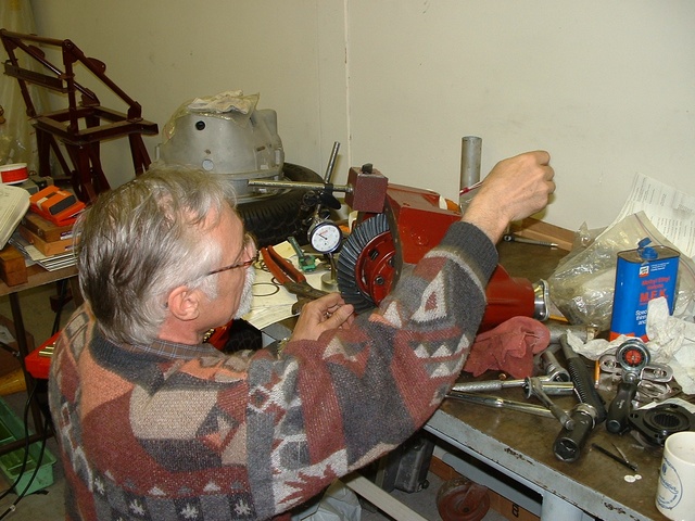
First Dick made this Torque tool so that we could check the drag on the bearings as we turned the pinion. The shop manual says that when the torque on the pinion flange nut is set, the pinion should show 8-12 inch pounds of drag on an appropriate tool Churchill number blah blah, Which of course everyone has laying around their shop. Dick had the torque screw driver and made cross bar out of stainless.
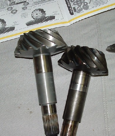
Further examination of the new and old pinion brought us to the conclusion that over the years slight changes were made in the dimension to take an oil slinger and baffle which were not in the earlier cars. On later applications this oil baffle and slinger were added and each was ~.030 thick. The missing .060 was now accounted for. Dick made a custom spacer to make up this extra space and we were back in business. Well almost, we also found that the original spacer and shims that went between the inner and outer bearing cones to prevent excess loading on the bearings was missing, so we made a custom spacer for this and cut it down until we got the correct pre load on the bearings to create 8-12 inch pounds of drag when the pinion nut was fully torqued down to 150 foot pounds. I think at this point we have about 20 custom parts in the Diff.
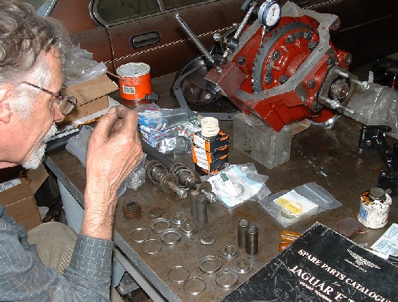
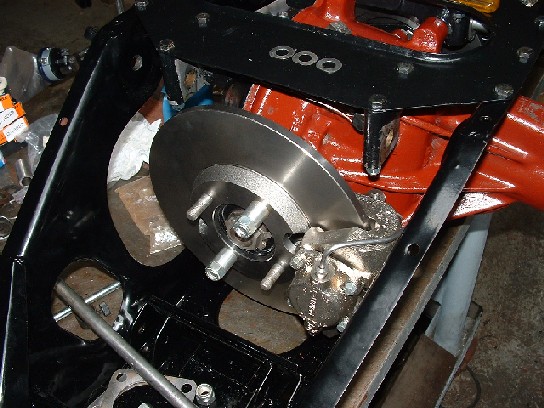
After the Diff was buttoned up we made quick progress on the rest of the IRS. I had already put the brakes together and most of the other work was done. previously. I did Powder coating on all the painted parts. Nickel plate on the steel parts. New brake lines, the hub bearings were done already. Here Dick is sorting out shims for the calipers. We had a heck of a time getting the calipers to go back into the cage until we determined that I had the wrong Rotors. 3.8L cars have a different Rotor than 4.2 cars.
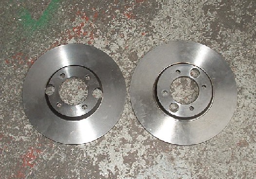
If you look closely You can see the difference. The Rotor on the Left is for 3.8L the one on the right is for 4.2L, Notice the holes in the center, these are required to bolt up the caliper. 3.8 Rotors are about .030 thinner and have a greater recess which allows the caliper to fit into the cage! We were scratching our heads for quite some time before we figured this out.
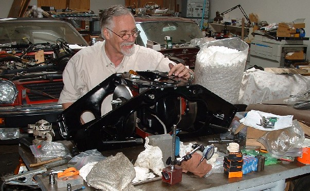
Getting all the right parts collected and in order for the lower control arms was fun. I have no idea what Jaguar was thinking on this design. It seems like they have five times more parts than are really needed! Notice the new parts at the back and the original parts up front. I was missing several small parts, and had to few of this and that. The usual!
Once the correct rotors were installed the brakes came together pretty quickly. The safety wires were a small challenge but nothing after the Diff setup. Notice the spacers on the rotor bolt shafts. These allowed us to torque down the rotor and get the caliper properly shimmed without the half shafts in place.
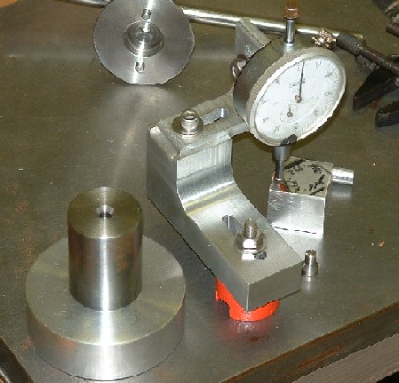
The next step was to setup the hub carrier bearings and shim up these to have the right amount of end play. Normally this is done with two spacers and shims, But we opted to make a custom spacer and cut it down to the exact right length. You can see two of the original spacers in the background. and in the front the new spacer, this goes between the bearings and is cut down to have no more than .002 of end play with the right torque of about 50 foot pounds on the shaft nuts.
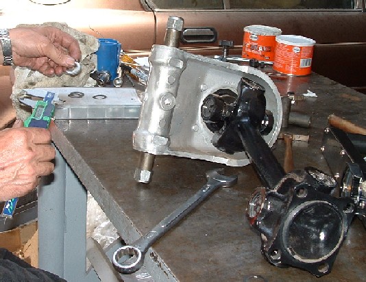
There is allot of this kind of work when setting up the IRS. Here we are trying to determine how much we need to cut off the custom made spacer by putting in temporary shims and checking the end play with dial caliper (not shown). We cut one of the original spacers in half and used it to simulate the forks of the fulcrum arms. After we get the right end play with the shims off of the custom spacer. Its good old fashioned trial and error.
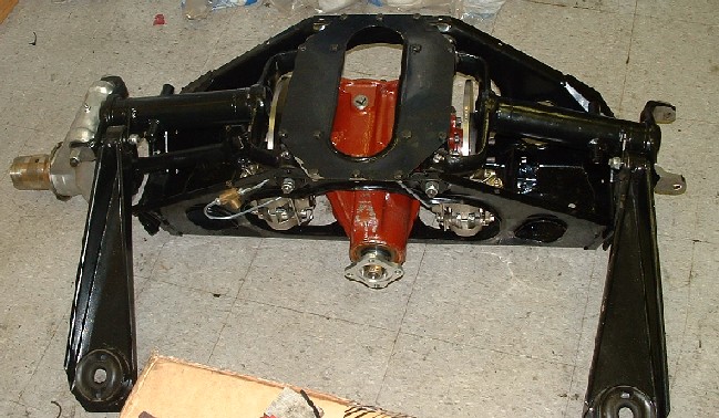
Once the hubs and control arm forks were setup, progress was quick and smooth. It took about an afternoon to get it all together and have the unit ready to go home and install on the car. I'm guessing that the entire IRS weighs 250 pounds, Not really practical to move with 2 men, I used an engine hoist to get it into and out of my car.
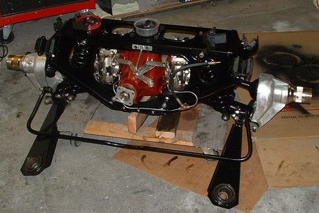
After I had the IRS back at home I put on the sway bar and mounting brackets. I spent a few hours fiddling with the emergency brake. The auto tightening feature is very primitive. I'm not sure what Jaguar was thinking with this setup but it is possibly one of the worst designs I've ever encountered. If it isn't perfectly installed and aligned it doesn't work. I used a furniture dolly to move the IRS in place, and to align it to the car on the dolly. I'll then lower the car onto the IRS.
First I had to get the wheels on the front so I could lower the car onto the ground, This was simple enough but seemed like a major milestone.
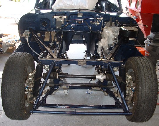
Next I rolled the IRS under and lowered the car down onto the IRS very very slowly. It snapped right in place. I used some small drifts and screw drivers to align the bolt holes and shimmed around the mounting blocks where there was extra space.
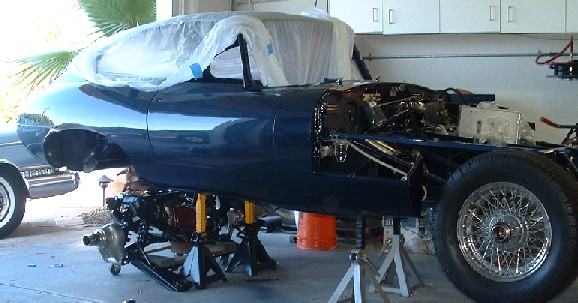
With the car on the Jack like this I could lower the body onto the IRS while it was sitting on the dolly very simply. The dolly can support the IRS and the shell if needed and has the natural tendency to align as the shell is lowered onto it. I have no idea why people try lifting the IRS up onto the car.
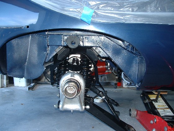
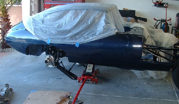
Here she is all bolted up and ready. The rest of the connections were simple enough. Sway bar, control arms, drive shaft brake line, and emergency brake cable. Went in without a hitch. The only difficult thing to get on is the nuts on the back of the rear Suspension mounts. These are nearly hidden when the IRS is installed, I used a long box end wrench and tape to hold the nut in place while I threaded it on from the outside.
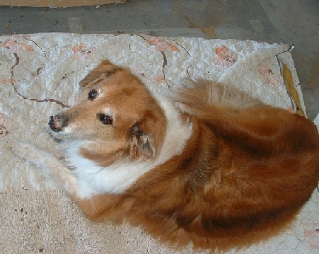
Here is the quality control supervisor, Jasper, watching the progress. Jasper spends many hours keeping me company and deserves honorable mention!